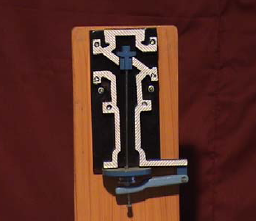
Dead Weight Safety Valve (TDL-0003)
SP Tech Equipments made Dead Weight safety valve consists of a valve which is made of gun metal to prevent rusting. It rests on the gun metal seat and is fixed to the top of a vertical steam pipe. The pipe has a flange F at the bottom for fixing at the top of the boiler shell. A weight carrier is suspended from the top of the boiler. It carries cast iron rings (i.e., weight). The total weight must be sufficient to the keep the valve on its seat against
the normal working pressure.
LIST OF EXPERIMENTS
To understand the working of Dead weight safety valve.
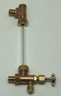
Water Guage Model(TDL-0004)
The quartz glass tubular water gauge fabricated by SP Tech Equipments is a primary meter of water level by using the optical principles and is applicable for steam drum of high and medium pressure boilers and water tanks. When water and steam coexisting in the water Side of the gauge is green in colour, the steam side is red in Full of water; the whole tube turns green, if the gauge is full of steam it turns red. Thus it has thoroughly
solved the problem of failure to display the sat us of full water or steam of other ordinary water Gauge and may avoid possible serious accident induced there by. The model simple in construction and convenient for maintenance.
LIST OF EXPERIMENTS
To understand the working of Water gauge.
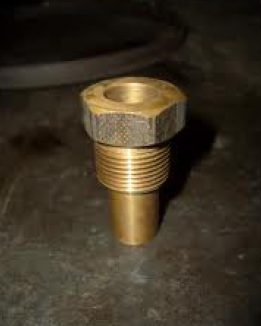
Fusible Plug Model (TDL-0005)
A fusible plug is a threaded metal cylinder usually of bronze, brass or gunmetal, with a tapered hole drilled completely through its length. This hole is sealed with a metal of low melting point that flows away if a pre-determined, high temperature is reached. The initial use of the fusible plug was as a safety precaution against low water levels in steam engine boilers, but later applications extended its use to other closed vessels, such as air conditioning systems and tanks for transporting corrosive or liquefied petroleum gasses.
LIST OF EXPERIMENTS
To understand the working of Fusible plug.
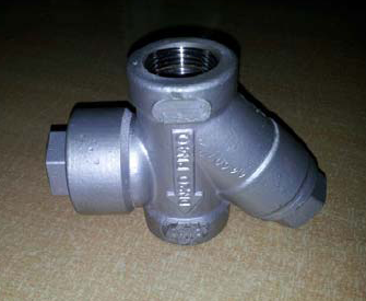
Expansion Steam Trap (TDL-0006)
Steam traps are automatic valves that release condensate from a steam space while preventing the loss of live steam. They also remove air and non condensable from the steam space. The liquid expansion steam trap employs a liquid expansion device to discharge condensate at a predefined temperature. It can easily be adjusted on site to any temperature within the operating range.
LIST OF EXPERIMENTS
To study and understand the working of Expansion steam traps.
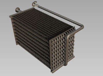
Economizer Model (TDL-0007)
Economizer are mechanical devices intended to reduce energy consumption, or to perform another useful function such as preheating a fluid. The term economizer is used for other purposes as well. Boiler, power plant, and heating, ventilating, and air-conditioning (HVAC) uses are discussed in this article. In simple terms, an economizer is a heat exchanger In boilers, economizers are heat exchange devices that heat fluids, usually water, up to but not normally beyond the boiling point of that fluid. Economizers are so named because they can make use of the enthalpy in fluid streams that are hot, but not hot enough to be used in a boiler, thereby recovering more useful enthalpy and improving the boiler’s efficiency.
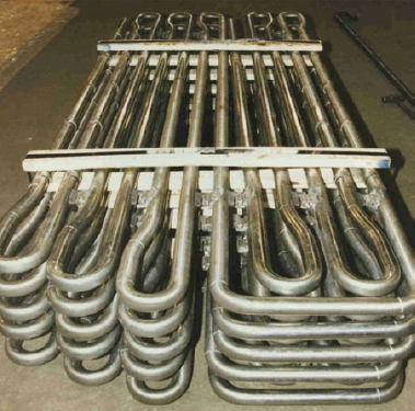
Steam Super Heater Model(TDL-0008)
A superheater is a device used to convert saturated steam or wet steam into dry steam used in steam engines or in processes, such as steam reforming. There are three types of superheaters namely: radiant, convection, and separately fired. A superheater can vary in size from a few tens of feet to several hundred feet (a few meters or some hundred meters).
LIST OF EXPERIMENTS
To study and understand the working of Steam Super Heater.
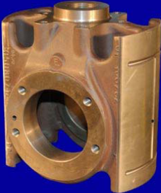
Cross Head (TDL-0009)
On smaller engines the connecting rod links the piston and the crankshaft directly, but this transmits sideways forces to the piston, since the crankpin (and thus the direction the force is applied) moves from side to side with the rotary motion of the crank. These transverse forces are tolerable in a smaller engine; a larger engine’s much greater forces would cause an intolerable degree of wear on the piston and cylinder, as well as increasing overall friction in the engine. A piston rod is attached to the piston and links it to the crosshead, which is a large casting sliding in crosshead guides allowing it only to move in the same direction as the piston travel. The crosshead also houses the gudgeon pin on which the small end of the connecting rod pivots. In this way, the transverse forces are applied only to the crosshead and its bearings, not to the piston itself.
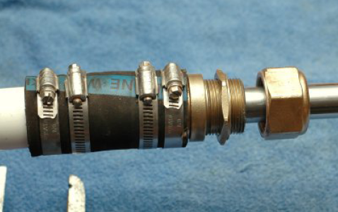
Stuffing Box (TDL-0010)
A stuffing box is an assembly which is used to house a gland seal. It is used to prevent leakage of fluid, such as water or steam, between sliding or turning parts of machine elements. A gland is a general type of stuffing box, used to seal a rotating or reciprocating shaft against a fluid. The most common example is in the head of a tap (faucet) where the gland is usually packed with string which has been soaked in tallow or similar grease. The gland nut allows the packing material to be compressed to form a watertight seal and prevent water leaking up the shaft when the tap is turned on. The gland at the rotating shaft of a centrifugal pump may be packed in a similar way and graphite grease used to accommodate continuous operation. The linear seal around the piston rod of a double acting steam piston is also known as a gland, particularly in marine applications.
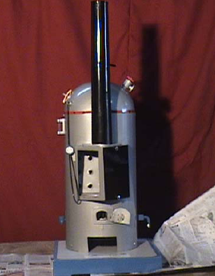
Cochran Boiler(TDL-0011)
The Cochran boiler was produced by Cochran & Co. of Annan, Scotland.] It is widely used in marine practice, either fired directly by coal or oil fuels, or else used for heat recovery from the exhaust of large diesel engines. Where such a boiler may be heated either by the exhaust gases of the main propulsion plant, or else separately fired when in port (usually by oil rather than coal) it is referred to as a composite boiler. The boiler is a cylindrical vertical water drum with a hemispherical domed top. This domed shape is strong enough not to require staying.
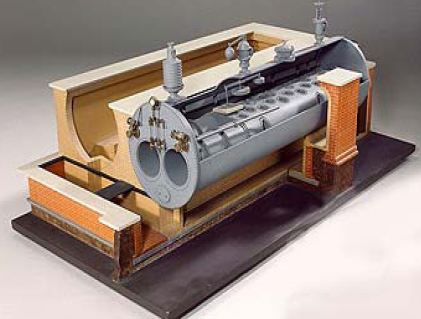
Lancashire Boiler (TDL-0012)
A Lancashire boiler is a double fire tube boiler, internally fired, horizontal, natural
draught and natural circulation type of boiler. This boiler is very popular and reliable because of simplicity of design and ease of operation. The boiler has good steaming quality, and coal of inferior quality can be used. It has low maintenance and operating cost. This boiler is widely used in sugar mills and chemical industries. This boiler is used where large reservoir of water and steam are required. The Lancashire boiler is similar to the Cornish, but has two large flues containing the fires instead of one Lancashire boilers often show corrugated flues, which absorb thermal expansion without straining the riveted seams.
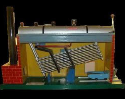
Model of Babcock & Wilcox Boiler (TDL-0013)
It is a water tube boiler. The shell is fitted with a super heater and with inclined water tubes over the furnace connected with headers. The model is fitted with stop valve, safety valve, water gauge, steam gauge, manhole, mud hole, regulating draught door, damper with counter weight and chimney. Seating and brick work are shown in wood work. The model is approximately one meter in length 28 cm. in breadth and 77 cm. high.
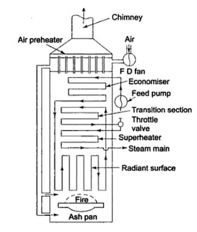
Benson Boiler Model (TDL-0014)
This boiler has a unique characteristic of absence of steam separating drum. The entire process of heating, steam generation and superheating is done in a single continuous tube. The presence of steam bubbles in contact with the surface of tubes seriously impairs heat transmission from the flue gases to water. By rising the boiler pressure to the critical pressure of steam (225 kgf/sq.cm.), this difficulty is overcome, as suggested by Mark Benson in 1922. At the critical pressure water and steam have the same density and no bubbles are formed. The first modern high pressure drum less boiler developed by Benson was put into operation in 1927 in West Germany power station.
Simple Carburetor (TDL-0015)
The carburetor controls the amount of fuel in relation to the amount of air that enters the engine. This is carried out by the deployment of a butterfly valve, which is linked in turn to the throttle pedal in the vehicle. The ratio of Fuel to Air is determined by the size of the holes in the “JETS” within the carburetor and is set by the engine designers. But other factors do come into play. The “choke” for example restricts the airflow in the carburetor and thus more fuel, in turn, is administered to the engine (necessary to compensate for the condensation of fuel inside a cold engine).
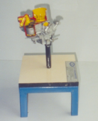
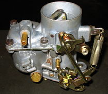
Solex Carburetor (TDL-0016)
This is self explanatory system mounted on stand. The original system of solex carburator will be used. This system will be dismantled & cut to demonstrate the operation of its components & all major subassembly.
S P Tech Equipments have designed the systems, keeping in consideration that all components are exposed & painted with different colours & reassembled on stand. The stand will be powder painted. This makes easy understanding of operation of system.
LIST OF EXPERIMENTS
Demonstration of solex carburetor.
 Chat with us